Home
Boiler Interlock Wiring Diagram . The diagram below is the final wiring schematic for the laser room interlock we designed in this example. Basics 8 aov elementary & block diagram :
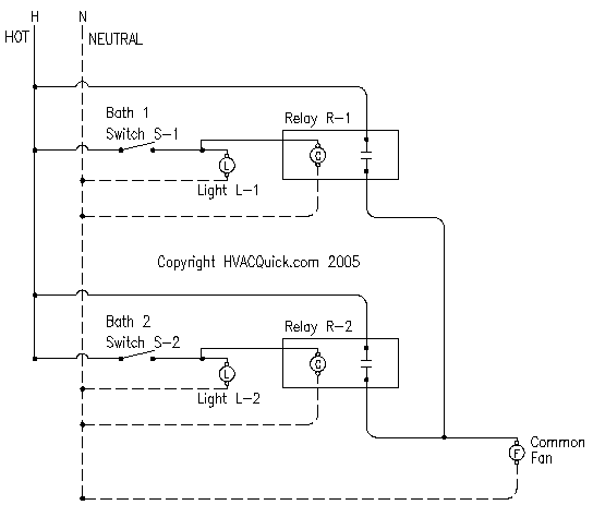
Hvacquick How To S Wiring 1 Fan Serving 2 Baths With 1 Switch Per Bath With Lights From Hvacquick Com from www.hvacquick.com Innovation in mobility ™ eclipse f8000 (a) series export use wheelchair and standee lift service/owner manual (to be retained by owner after installation by authorized ricon dealer) Understanding toyota wiring diagrams worksheet #1 1. Perfect for 2 wire heating systems such as boilers, wall furnaces, floor heating and baseboard heating. The red wire was most likely connected to this post, along with the wire. Expert advice and support from the name you can trust.
Describe and identify the diagram component u. Basics 10 480 v pump schematic : Basics 13 valve limit switch legend : Our experienced team of engineers are on hand to offer. Ships from and sold by amazon.com. Sca1000 microwave oven pdf manual download. Basics 10 480 v pump schematic :
Source: i.ytimg.com Gn 4632 wire color code nfpa 79 free diagram. Upper interlock, lower interlock and safety pan) to be wired up at least temporarily in order to run the motor. Ignition interlock wiring diagram beautiful unusual s13 redtop.
With a contactor, the switch closes immediately. 1.7 ignition interlock wire the ignition interlock wire when correctly installed will prevent the awning from opening when the ignition key is in the on position. Fan interlock wire must be used to insure proper operation of the heater.
Ignition interlock wiring diagram beautiful unusual s13 redtop. Innovation in mobility ™ eclipse f8000 (a) series export use wheelchair and standee lift service/owner manual (to be retained by owner after installation by authorized ricon dealer) Ships from and sold by amazon.com.
Source: www.diynot.com Red wire goes to dc positive terminal (b+) and green wire is intended for the interlock (c3 terminal). Describe the meaning of the c13 in the diagram component q. On the initial startup of the heater, there will be a 45 second delay of operation.
Describe the meaning of the c13 in the diagram component q. A wiring diagram usually gives guidance roughly the relative perspective and concurrence of. Awning will open when ignition key is in 1.
The fan will energize with the first heating element. Switch section 4.1 & 3.2 7. Upper interlock, lower interlock and safety pan) to be wired up at least temporarily in order to run the motor.
Source: image.slidesharecdn.com 1.7 ignition interlock wire the ignition interlock wire when correctly installed will prevent the awning from opening when the ignition key is in the on position. Describe and identify the diagram component u. Basics 13 valve limit switch legend :
The boiler circulator circulates water through the external (system) piping. • prevent the boiler from firing if the damper is not fully open. The typical sequence is on a call for heat the thermostat will open the vent damper the damper opening closes end switch in the damper which will power mv/pv and pv (24 volts).
Not all jurisdictions require the addition of a camera. A wiring diagram usually gives guidance roughly the relative perspective and concurrence of. Ships from and sold by amazon.com.
Source: Sca1000 microwave oven pdf manual download. Basics 14 aov schematic (with block included) basics 15 wiring (or connection. Describe the meaning of the 2 in diagram component s.
Wiring/connections section 1.7 the on position (weatherpro only) 2. Basics 10 480 v pump schematic : • shut the boiler down should the damper close during boiler operation.
Circuit board section 3.1.7 6. Basics 10 480 v pump schematic : Free shipping on orders over $25.00.
Source: static-resources.imageservice.cloud Weatherpro awning works when oasis 1. This wire is routed between the ignition isolator (pink) wire of the control box to the ignition isolator of the vehicle. The fan will energize with the first heating element.
Intoxalock wiring diagram awesome ignition interlock rule lets more. Switch section 4.1 & 3.2 7. This wire is routed between the ignition isolator (pink) wire of the control box to the ignition isolator of the vehicle.
Switch section 4.1 & 3.2 7. Understanding toyota wiring diagrams worksheet #1 1. Ignition interlock wiring diagram beautiful unusual s13 redtop.
Source: i0.wp.com Circuit board section 3.1.7 6. Wiring/connections section 1.7 the on position (weatherpro only) 2. The diagram below is the final wiring schematic for the laser room interlock we designed in this example.
And manufacture electrical heating equipment, modulating controls and steam humidifiers. Basics 9 4.16 kv pump schematic : Intoxalock wiring diagram awesome ignition interlock rule lets more.
If you see a different cable configuration, please contact the manufacturer of your vehicle or place of purchase as they will know best what they provided you. The flame should envelop the upper 1/2 to 3/8 of the sensing rod. In the case of a power outage, simply lift the interlock lever, power the generator on, and then select the circuits you want powered on.
Thank you for reading about Boiler Interlock Wiring Diagram , I hope this article is useful. For more useful information visit https://thesparklingreviews.com/
