Home
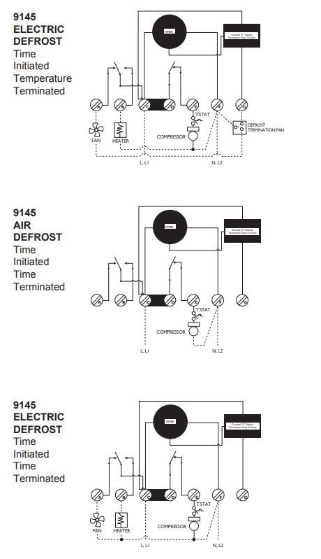
Paragon Defrost Timer Wiring Diagram . Defrost timer wiring codes etc. Variety of walk in freezer defrost timer wiring diagram.
Paragon Commercial Defrost Timer Digital from d1mv2b9v99cq0i.cloudfront.net Connect wiring according to the. Insert plugs into holes (b). When i was a little unsure about hooking those defrost timers up, where the timer motor wire went , #1 terminal or # 2 terminal. Paragon 8145 00 wiring diagram defrost timer wire diagram wiring schematic database 16 1 rh hastalavista me frigidaire refrigerator wiring diagram 1f. These dependable time switches can handle electrical loads up to 40 a per pole and allow for up to 12 on/off operations per day.
Each pin has its own function in the operation of the timer. I like blue for stat & noid, yeller on the clock, red for fans, and black for heater, just cause everyone else liked red for heaters. This is your ground / neutral wire. Honeywell universal electronic fan time st9120u1011. Paragon 8145 00 wiring diagram defrost timer wire diagram wiring schematic database 16 1 rh hastalavista me frigidaire refrigerator wiring diagram 1f. When i was a little unsure about hooking those defrost timers up, where the timer motor wire went , #1 terminal or # 2 terminal. Paragon 00 wiring diagram defrost timer circuit evaporator.
Source: This is your ground / neutral wire. Insert plugs into holes (b). Honeywell universal electronic fan time st9120u1011.
When in defrost mode, the power (pin 1) connects to pin 2, which activates the defrost mode. Defrost timer wiring codes etc. For electric heat, hot gas or compressor shutdown defrost.
With today's busy lifestyles, everyone looks for products that provide convenience. A wiring diagram is a simple visual representation of the physical connections and physical layout of an electrical system or circuit. It shows how the electrical wires are interconnected and can also show where fixtures and components may be connected to the system.
Source: The t100 series mechanical time switch has proven it can stand the test of time. Service call on a walk in freezer not working in this video i explain how the electric defrost system works in detail. Defrost timer wiring codes etc.
The dtav40 defrost control automatically selects the appropriate voltage between wiring diagrams. For electric heat, hot gas or compressor shutdown defrost. Whirlpool tech line gave me an easy way out:
Each pin has its own function in the operation of the timer. When i was a little unsure about hooking those defrost timers up, where the timer motor wire went , #1 terminal or # 2 terminal. It shows the elements of the circuit as streamlined forms, and also the power and also signal links in between the devices.
Source: itj.ibr600tonido.pw A wiring diagram is a streamlined standard pictorial depiction of an electrical circuit. If the timer has a white wire going to it ,the timer lead goes on #1 anything else goes on #2 These dependable time switches can handle electrical loads up to 40 a per pole and allow for up to 12 on/off operations per day.
A wiring diagram is a streamlined standard pictorial depiction of an electrical circuit. User manuals, grasslin timer operating guides and service manuals. For editing my videos i use adobe prem.
The t100 series mechanical time switch has proven it can stand the test of time. A wiring diagram is a streamlined standard pictorial depiction of an electrical circuit. A wiring diagram is a simple visual representation of the physical connections and physical layout of an electrical system or circuit.
Source: www.appliance411.com Most defrost timers stay in defrost mode for 30 minutes. Variety of walk in freezer defrost timer wiring diagram. The t100 series mechanical time switch has proven it can stand the test of time.
A wiring diagram is a simple visual representation of the physical connections and physical layout of an electrical system or circuit. If the timer has a white wire going to it ,the timer lead goes on #1 anything else goes on #2 Intermatic/grässlin's defrost controls just got even better!
The grässlin dtav40 series auto voltage defrost timer is applicable to air defrost (compressor. Paragon 00 wiring diagram defrost timer circuit evaporator. A wiring diagram is a simple visual representation of the physical connections and physical layout of an electrical system or circuit.
Source: This is your ground / neutral wire. If the timer has a white wire going to it ,the timer lead goes on #1 anything else goes on #2 Each pin has its own function in the operation of the timer.
Variety of walk in freezer defrost timer wiring diagram. Black is also popular for the line too. Service call on a walk in freezer not working in this video i explain how the electric defrost system works in detail.
Honeywell universal electronic fan time st9120u1011. The grässlin dtav40 series auto voltage defrost timer is applicable to air defrost (compressor. User manuals, grasslin timer operating guides and service manuals.
Source: s3.amazonaws.com When in defrost mode, the power (pin 1) connects to pin 2, which activates the defrost mode. Or / vac, 60 hz heater. A wiring diagram is a simple visual representation of the physical connections and physical layout of an electrical system or circuit.
The paragon® series auto voltage defrost timer is designed for commercial freezers wiring diagrams. I like blue for stat & noid, yeller on the clock, red for fans, and black for heater, just cause everyone else liked red for heaters. When in defrost mode, the power (pin 1) connects to pin 2, which activates the defrost mode.
Insert plugs into holes (b). With today's busy lifestyles, everyone looks for products that provide convenience. Or / vac, 60 hz heater.
Thank you for reading about Paragon Defrost Timer Wiring Diagram , I hope this article is useful. For more useful information visit https://thesparklingreviews.com/
