Home
Foundation Fieldbus Wiring Diagram . Remove the usb cable from the trex unit before connecting to a device. A fieldbus segment is made up of one or more segments.
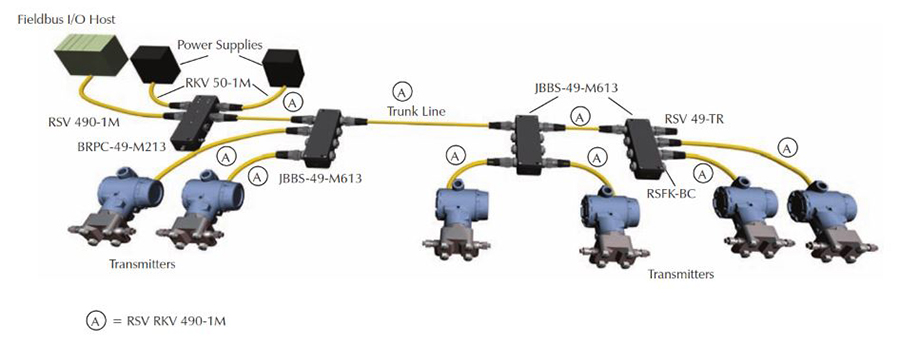
Foundation Fieldbus Design Guide Valin from files.valinonline.com For specials or if you can't find what you want, please contact rotork. Ian verhappen and augusto pereira; A typical ff jb arrangement is shown in fig below. Provide operators with an interface allowing indication and adjustment of control parameters. Wiring diagram, terminal plan project data:
Fieldbus foundation 9005 mountain ridge drive, bowie bldg. A truly redundant wiring solution for foundation fieldbus segments. Touch device users, explore by touch or with swipe gestures. It demonstrates the proper cutting, stripping, crimping and shrinking tec. Signal transmission via fieldbus interface. The trex unit draws approximately 12 ma from the fieldbus segment when it is online. A temperature transmitter, for example, has a completely different set of capabilities and parameters than a control valve.
Source: blog.isa.org Ff (foundation fieldbus) junction box. Ff junction box generally contains. For wiring between the transmitter and sensor, verify the maximum cable length does not exceed 1,000 ft (305 m).
Provide operators with an interface allowing indication and adjustment of control parameters. To power a foundation fieldbus device, the trex unit needs the foundation fieldbus power plug. Before the introduction of foundation fieldbus, the gateway to the industrial automation started with parallel wiring, where the devices were connected independently with the rule and control level.
Foundation fieldbus is the ultimate realization of this trend, where the field instruments themselves can do all necessary control functions. Foundation fieldbus is the ultimate realization of this trend, where the field instruments themselves can do all necessary control functions. This video gives an overview of the proper techniques for wiring fieldbus h1 cable.
Source: instrumentationtools.com One of the casualties of the new fieldbus paradigm is the traditional loop diagram (or loop sheet), the purpose of which is to document the signal wiring dedicated for each measurement and control loop. Remove the usb cable from the trex unit before connecting to a device. However, with the increased levels of automation, the number of participants also increased.
The current and h1 device signal travel on the same line. For wiring between the transmitter and sensor, verify the maximum cable length does not exceed 1,000 ft (305 m). Because of the many variables and.
One of the casualties of the new fieldbus paradigm is the traditional loop diagram (or loop sheet), the purpose of which is to document the signal wiring dedicated for each measurement and control loop. The current and h1 device signal travel on the same line. In foundation fieldbus, the control loop is virtual rather than physical, being comprised of digital data sent between field.
Source: image.slidesharecdn.com Before the introduction of foundation fieldbus, the gateway to the industrial automation started with parallel wiring, where the devices were connected independently with the rule and control level. Spur termination board and field barrier. Here, the only necessary purposes served by the dcs are:
The trex unit draws approximately 12 ma from the fieldbus segment when it is online. A truly redundant wiring solution for foundation fieldbus segments. Wiring diagrams for foundation fieldbus devices and the field communicator application.
Device description file for use with foundation fieldbus module ff01 mk2 rev2 itk5.1 Project name, 2 freely definable customer fields with a max. For those wanting information about how fieldbus works to control a process, refer to:
Source: files.valinonline.com The examples and diagrams in this manual are included solely for illustrative purposes. One of the casualties of the new fieldbus paradigm is the traditional loop diagram (or loop sheet), the purpose of which is to document the signal wiring dedicated for each measurement and control loop. Ff (foundation fieldbus) junction box.
In foundation fieldbus, the control loop is virtual rather than physical, being comprised of digital data sent between field. This led to a high wiring expenditure. The integrated communication interfaces, programmable logic controllers (plcs) and diagnostic features help your systems run smoothly, reducing unplanned outages.
Project name, 2 freely definable customer fields with a max. The integrated communication interfaces, programmable logic controllers (plcs) and diagnostic features help your systems run smoothly, reducing unplanned outages. Ff junction box generally contains.
Source: web-material3.yokogawa.com Remove the usb cable from the trex unit before connecting to a device. For specials or if you can't find what you want, please contact rotork. The examples and diagrams in this manual are included solely for illustrative purposes.
Ff junction box generally contains. Wiring diagrams for foundation fieldbus devices and the field communicator application. In fact, given the right ff system design, the dcs.
Remove the usb cable from the trex unit before connecting to a device. (the trex unit draws 0 ma when it is offline.) For wiring between the transmitter and sensor, verify the maximum cable length does not exceed 1,000 ft (305 m).
Source: 4.bp.blogspot.com Apt (analog position transmitter) att (analog torque transmitter) apt & att (both position and torque) motor contactor: For wiring and installing a foundation fieldbus network. The current and h1 device signal travel on the same line.
Ensure that you use the following cables for the different connections: Ian verhappen and augusto pereira; Fieldbus valve systems are replacing conventional hardwired solutions.
Device description file for use with foundation fieldbus module ff01 mk2 rev2 itk5.1 A truly redundant wiring solution for foundation fieldbus segments. The fieldbus foundation.the aim of the fieldbus foundation was and is to create a single, international fieldbus standard for hazardous environments which will find
Thank you for reading about Foundation Fieldbus Wiring Diagram , I hope this article is useful. For more useful information visit https://thesparklingreviews.com/